
Semiconductor equipment display sizes vary across compact process modules, wafer-handling systems, inspection stations, control cabinets, packaging machines, and engineering terminals. These applications do not share one standard size because their operator tasks, software layouts, viewing distances, and image-detail requirements are different.
A 7-inch touchscreen may suit a local status panel, while 12.1-inch or 15-inch LCDs provide more room for recipes and alarms. Inspection stations may require 21.5-inch, 23.8-inch, 27-inch, or larger displays for images, maps, graphs, and multiple windows.
After more than ten years of working with industrial LCD projects, we have found that diagonal size alone is not a reliable selection method. The decision should also include active area, outline, aspect ratio, native resolution, viewing distance, touch-target dimensions, connector clearance, and long-term availability.
The best display is not automatically the largest that fits. It is the smallest practical configuration that presents information clearly, supports accurate interaction, fits the equipment, and remains controlled throughout production and service.
Quick Answer: Common display sizes in semiconductor equipment include 5, 7, 8, 10.1, 10.4, 12.1, 15, 15.6, 17, 18.5, 19, 21.5, 23.8, and 27 inches. Smaller sizes are often used for local controls and service panels. Medium sizes suit process HMIs, recipe management, alarms, and machine setup. Larger displays are useful for wafer inspection, metrology, engineering review, and multi-window interfaces. The final choice must be based on software resolution, active area, viewing distance, touch operation, enclosure dimensions, host interface, and lifecycle requirements rather than diagonal size alone.
Claim: Semiconductor equipment display size is a system-level decision. The correct size connects HMI content, software resolution, operator position, touch method, machine structure, host electronics, thermal conditions, production lifecycle, and field-service strategy.
1. Which Display Sizes Are Common in Semiconductor Equipment?
Semiconductor equipment manufacturers use many TFT LCD sizes because a local controller and an inspection workstation perform different functions. These ranges are design directions, not industry standards.
Direct answer: Displays from approximately 5 to 10.4 inches are common for compact control and service interfaces. Sizes from 12.1 to 19 inches are widely applicable to machine HMIs and legacy equipment formats. Displays from 21.5 to 27 inches or larger are often selected when inspection images, wafer maps, process trends, or several software windows must remain visible at the same time.
Where Are 5-Inch to 8-Inch Displays Used?
Compact LCDs are useful when a machine needs a local operating point near a module, load port, pump, robot, chemical-delivery unit, or service access area. The interface may show equipment state, a small group of values, maintenance commands, alarm acknowledgment, or manual movement controls.
Common resolutions in this category can include 800 × 480, 1024 × 600, or other panel-specific formats. Engineers should verify that the HMI can present text and controls clearly at the native resolution without creating crowded touch targets.
A small touchscreen also requires careful ergonomic review. Operators wearing cleanroom gloves need sufficient spacing between controls. A compact diagonal size is useful only when the workflow can remain simple and deliberate.
Why Are 10.1-Inch, 10.4-Inch, and 12.1-Inch Displays Practical?
These sizes provide a balance between usable screen area and mechanical integration. A 10.1-inch widescreen panel may suit a modern graphical interface, while 10.4-inch and 12.1-inch 4:3 panels remain relevant to equipment designed around established industrial software layouts.
Representative native resolutions include 1280 × 800 for many widescreen panels and 1024 × 768 for many 4:3 panels. The 4:3 format can suit vertically organized or legacy software, while widescreen formats provide more horizontal space for navigation and trends.
These displays may be used in compact process tools, environmental systems, wafer-handling controls, subsystem HMIs, and production equipment where the operator stands close to the machine.
When Are 15-Inch to 19-Inch Displays Selected?
Medium industrial displays are suitable for primary machine-control interfaces because they can present more information without requiring a very large front panel. Common formats include 15-inch 4:3, 15.6-inch 16:9, 17-inch 5:4, 18.5-inch 16:9, and 19-inch 5:4.
Resolutions such as 1024 × 768, 1280 × 1024, 1366 × 768, and 1920 × 1080 may be encountered. This category is important for replacement projects because many machines were built around 4:3 or 5:4 industrial displays.
Changing a legacy 15-inch or 19-inch interface to a modern widescreen panel can alter active-area alignment, software scaling, mounting, and touch-button placement. A larger diagonal measurement does not guarantee a larger usable height. Engineers should compare active width and height directly.
Why Do Inspection Stations Use 21.5-Inch to 27-Inch Displays?
Wafer inspection and metrology software may present camera images, wafer maps, defect coordinates, measurement graphs, classification results, and tool status. Larger Full HD or higher-resolution displays provide more room for these elements.
These sizes can also suit engineering stations used for recipe development, diagnostics, data review, and equipment setup. Resolution should match the source image, software scaling, viewing distance, and importance of the displayed detail.
More pixels do not automatically improve usability. If software does not scale correctly, controls and text can become too small. Inspection applications should be validated using the final software and representative image content, as explained in How Do LCD Displays Improve Wafer Inspection Systems?.
| Display Range | Typical HMI Direction | Important Engineering Check |
|---|---|---|
| 5–8 inches | Local status, subsystem control, maintenance access | Text readability and gloved touch-target size |
| 10.1–12.1 inches | Compact process HMI, recipes, alarms, equipment setup | Widescreen versus 4:3 software layout |
| 15–19 inches | Primary machine control, multi-page HMI, legacy replacement | Active area, aspect ratio, mounting, and host timing |
| 21.5–27 inches | Inspection, metrology, engineering review, multi-window software | Resolution, scaling, viewing distance, and image quality |
| Above 27 inches | Specialized review stations or shared visualization | Operator workflow, heat, support structure, and service access |
The table is a starting point. Two machines using the same size may still need different brightness, viewing angle, temperature range, touch technology, interface, and lifecycle control.
Claim: Common semiconductor display sizes range from compact local panels to large inspection monitors, but each size category represents an HMI function rather than a universal specification. The software and operator workflow should define the required active area before the enclosure is finalized.
2. How Should Engineers Select the Correct Display Size?

Screen size should be selected through a sequence of software, ergonomic, mechanical, electrical, optical, and lifecycle checks. Beginning with a preferred diagonal measurement can hide conflicts that become expensive after the enclosure and touchscreen tooling are completed.
Direct answer: Engineers should define the HMI content, smallest readable information, normal viewing distance, operator position, touch method, glove requirement, software resolution, aspect ratio, active-area target, enclosure opening, host interface, and expected lifecycle before approving a display size.
How Does HMI Content Determine Screen Area?
The interface should separate permanent information from task-specific pages. Machine state, alarms, current recipe, wafer or lot identification, and navigation may remain visible, while diagnostics, service logs, and calibration pages can appear when required.
If too much content remains visible, a small display can force reduced text or frequent page changes. A workflow review should decide what the operator needs at each step before more screen area is added.
Why Must Resolution Be Considered with Size?
Diagonal size describes physical dimensions; resolution describes the pixel matrix. A 15.6-inch Full HD panel and a 21.5-inch Full HD panel show the same number of pixels at different physical sizes. The smaller panel has greater pixel density, which can make unscaled text and controls physically smaller.
Scaling should be tested on the intended operating system, graphics hardware, and HMI application. Engineers should review text, icons, images, graphs, keyboards, and windows at the native panel resolution.
How Do Aspect Ratio and Active Area Affect Replacement?
Displays with the same diagonal size can have different aspect ratios and active-area dimensions. A 4:3 panel provides more height relative to width than a 16:9 panel. A 5:4 panel has another geometry. This difference affects the visible opening, glass printing, software layout, and location of touch controls.
For a replacement project, engineers should compare active width, active height, outline, thickness, mounting points, connector position, and viewing direction. A new panel should not be described as a drop-in replacement until these items and the electrical requirements have been verified.
Detailed lifecycle considerations are discussed in Why Is Long-Term Availability Critical in Semiconductor Manufacturing Equipment?.
How Do Viewing Distance and Mounting Height Change the Decision?
A display near a service point can be smaller than one intended to show machine status from several steps away. Engineers should evaluate the operator position, reach, line of sight, obstructions, viewing angle, and cleanroom-lighting reflections.
How Does Touch Operation Influence Size?
Touchscreen size should support the intended control dimensions and spacing. Gloves or a stylus can change the required target area and touch technology. PCAP performance also depends on the cover glass, firmware, grounding, power environment, and glove material.
A larger screen does not correct a poorly organized HMI. The touch layout should avoid placing critical controls too close together and should provide clear confirmation for commands. Emergency stops, safety interlocks, and safety-rated actions should remain separate from the software-controlled touchscreen where required by the equipment design.
Why Should Engineers Review the Complete Mechanical Stack?
The panel outline is only one layer. The assembly may include the LCD, touch sensor, cover glass, bonding material or air gap, gasket, frame, controller, cables, fasteners, and enclosure.
The drawing should identify the active area, visible opening, glass outline, thickness, mounting, connector access, cable-bend area, controller position, and service-removal path. Mounting pressure should not distort the active display area.
A structured requirement process is provided in How Do Engineers Select Displays for Semiconductor Machines?.
Claim: Correct size selection begins with the operator task and native software layout, then confirms physical fit, touch usability, viewing conditions, electrical compatibility, and lifecycle support. Diagonal size should summarize a validated design, not replace the design process.
3. Which Display Sizes Suit Different Semiconductor Machines?
Different semiconductor processes generate different information. A deposition system, wafer sorter, inspection station, die bonder, and automated test system may all use industrial LCDs, but the correct display architecture depends on what operators and technicians must accomplish at the machine.
Direct answer: Compact displays suit local and subsystem controls. Medium displays suit primary process HMIs and established industrial software. Larger displays suit inspection, metrology, analytics, and engineering workflows. Equipment function should define the required information density before a specific panel model is selected.
What Sizes Suit Process Equipment HMIs?
Etching, deposition, cleaning, thermal processing, implantation, and related process tools may display chamber state, recipe steps, temperature, pressure, gas flow, vacuum conditions, robot position, alarms, and maintenance information.
A 10.1-inch to 19-inch display may be practical for many local process HMIs. A single-module unit may need less area, while a multi-chamber machine may benefit from a larger overview.
The role of local machine displays is examined in Why Do Semiconductor Machines Require Industrial LCDs?.
What Sizes Suit Wafer Handling and Automation?
Wafer-handling systems, load ports, sorters, transfer modules, and factory-automation equipment may use a small local panel for status and manual operation or a medium HMI for route, carrier, sensor, robot, and alarm information.
Displays between 7 and 15.6 inches can support many of these tasks when the interface is focused. Additional area may be justified when one terminal controls several modules or detailed diagnostics.
What Sizes Suit Wafer Inspection and Metrology?
Inspection and metrology systems often benefit from 21.5-inch, 23.8-inch, 27-inch, or larger screens because operators may need to compare captured images, wafer maps, defect markers, measurement regions, graphs, and classification data.
If the screen only confirms instrument operation, a smaller panel may be sufficient. If engineers make decisions from the displayed image, resolution, grayscale, contrast, color behavior, viewing angle, reflection, and calibration require additional evaluation.
What Sizes Suit Semiconductor Packaging and Test Equipment?
Die-bonding, wire-bonding, dispensing, molding, marking, inspection, and automated test equipment may use displays from approximately 10.1 to 21.5 inches. The correct size depends on whether the interface emphasizes production status, camera alignment, machine setup, test results, or several functions together.
Vision-assisted alignment may require more image area than a recipe interface. Increasing diagonal size without improving camera resolution or software layout, however, does not create additional image information.
How Do Cleanroom Conditions Affect the Size Choice?
A larger front surface requires more cover glass, stronger support, and careful review of sealing, reflection, and repeated cleaning.
Projected capacitive touch can support a continuous glass front, but its performance must be tested with the real cover glass, gloves, enclosure, grounding, and electrical environment. Environmental considerations are covered in How Do Cleanroom Conditions Affect Semiconductor Equipment Displays?.
Claim: Display size should follow machine function. Local controls prioritize compact integration and deliberate touch operation; process HMIs balance overview with enclosure space; inspection and engineering stations prioritize image area, resolution, and multi-window usability.
4. How Should Display Size Be Validated and Controlled?
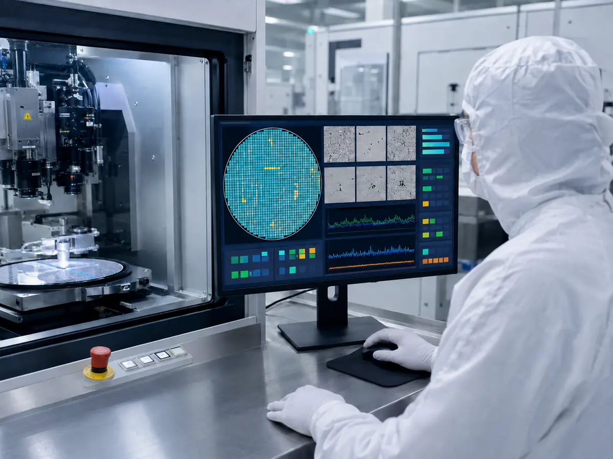
A candidate display should be evaluated in the complete equipment configuration. A panel that appears suitable in a datasheet can still create software scaling, thermal, reflection, touch, cable, or service problems after installation.
Direct answer: Engineers should validate the proposed size with final HMI software, representative images, the intended host computer, production cables, touchscreen, cover glass, enclosure, mounting, grounding, facility lighting, operating temperature, cleaning procedure, and service method. The approved model and all related parts should then be controlled as one configuration.
What Should Be Checked on the First Sample?
The first sample should confirm native resolution, timing, image stability, startup, sleep recovery, brightness control, touch communication, edge accuracy, glove operation, connector retention, and repeated power cycling.
Engineers should review every important page, including the smallest text, alarms, keyboard, graphs, images, language expansion, and remote-access behavior.
How Should Mechanical Fit Be Verified?
A drawing should be compared with the real enclosure or a mechanical prototype. Confirm the opening, active-area alignment, glass border, mounting pressure, total thickness, cable direction, controller clearance, fastener access, and removal path.
Use the intended gasket and frame. Excessive pressure can cause light leakage, mura, touch problems, or mechanical stress. Large panels may need support that does not press on the active area.
Why Must Thermal and Electrical Testing Use the Final Machine?
Display temperature inside an enclosure can exceed room temperature because of the backlight, host computer, power supply, controller, and nearby components. Larger or brighter displays can add heat.
Check touch and image behavior while motors, pumps, robots, lighting, heaters, power supplies, and communication modules are active. Cable routing, shielding, grounding, interface type, and power quality can affect results.
Relevant LCD, touch, bonding, and interface options are compared in What Display Technologies Are Used in Semiconductor Equipment?.
How Should the Approved Configuration Be Documented?
The controlled record should identify the LCD model and revision, touchscreen, touch-controller firmware, cover-glass drawing, bonding, display controller, cables, power, backlight settings, software resolution, mechanical drawing, and validation results.
Incoming inspection should verify model identity, dimensions, active-area alignment, cosmetic condition, glass printing, connector position, image quality, brightness, touch communication, and packaging condition according to agreed criteria.
How Should a Size Change or Replacement Be Managed?
A replacement analysis should compare the original active area, outline, mounting, aspect ratio, resolution, interface, connector, power, timing, backlight, viewing angle, temperature range, touchscreen, glass, cables, controller, and software behavior.
If no true drop-in replacement exists, a controlled modification may be necessary. A new cable, controller, bracket, cover glass, or software layout can be acceptable when the changes are clearly documented and validated. Presenting a panel as compatible based only on diagonal size can transfer hidden risk into production and service.
Why Should Lifecycle Be Considered Before Size Is Frozen?
Product status must be checked at model level. Engineers should consider production start, annual demand, project duration, service period, alternatives, change notification, last-buy planning, and storage.
A custom touchscreen and cover glass should not be designed so tightly around one panel that every small revision forces complete tooling changes. Where practical, mechanical tolerances, cable strategy, and controller architecture can provide controlled flexibility without weakening validation.
Claim: Display size is approved only after the complete assembly works with the final software, electronics, enclosure, touch method, lighting, cleaning process, and thermal environment. Configuration records and lifecycle planning then protect the approved design throughout production and field service.
5. What Advantages Does XIANHENG Offer for Semiconductor Display Projects?
XIANHENG supports display projects for semiconductor processing, wafer handling, inspection, metrology, cleanroom automation, packaging, bonding, and testing equipment. Our work can begin with an existing panel model, a mechanical opening, an HMI resolution, or an early equipment concept.
Direct answer: XIANHENG can help semiconductor equipment manufacturers compare display sizes, active areas, aspect ratios, resolutions, interfaces, mechanical outlines, touchscreen structures, cover glass, optical bonding, controllers, cables, and lifecycle conditions. The objective is to recommend a complete display configuration that can be prototyped, validated, produced, and serviced.
Which Display Size Options Can XIANHENG Support?
XIANHENG can provide compact, medium, and large industrial TFT LCDs from manufacturers such as BOE, AUO, Innolux, and Tianma. Options vary in resolution, brightness, viewing angle, temperature range, interface, and lifecycle.
We can evaluate widescreen panels for modern HMIs, 4:3 and 5:4 formats for established equipment, high-resolution panels for inspection interfaces, and wide-temperature or high-brightness options when the application requires them.
Customers can review available models through the Industrial LCD Product Collection.
How Can XIANHENG Compare Candidate Sizes?
Our engineers can compare active area, outline, mounting, resolution, aspect ratio, interface, connector, power, brightness, viewing angle, temperature range, and product status.
This shows whether a larger panel provides useful area, requires HMI changes, and fits the enclosure and cable path.
How Can the Touchscreen and Cover Glass Be Customized?
XIANHENG supports projected capacitive or resistive touchscreens with custom sensor dimensions, cover glass, printing, holes, edge processing, surface treatment, FPC, cable, interface, and firmware.
PCAP performance can be developed around the LCD, cover glass, gloves, enclosure, grounding, and electrical environment. Optical bonding is available for reduced internal reflection and a more integrated front assembly.
Which Integration Formats Can XIANHENG Provide?
Depending on the architecture, XIANHENG can support a standalone LCD, touch-display assembly, optical bonding, custom cables, controller board, open-frame display, panel-mount monitor, or integrated HMI assembly.
Interface, connector, cable direction, power, active-area alignment, controller placement, cover-glass drawing, mounting, and service access can be reviewed before samples are prepared.
How Does XIANHENG Support Validation and Production?
Prototype support can include candidate confirmation, drawing review, custom touch and glass, bonding, cables, controller selection, and sample assembly. We can also help investigate image, touch, power, thermal, reflection, and fit issues.
After approval, the configuration can be recorded according to the agreed bill of materials and revision. Production support can include incoming acceptance criteria, packaging, delivery coordination, change communication, replacement comparison, and demand planning.
The broader support process is explained in How Can XIANHENG Support Semiconductor Equipment Manufacturers?.
What Information Should Customers Provide?
For an efficient recommendation, customers should send the application, HMI screenshots, software resolution, viewing distance, touch and glove requirements, available space, drawing, host-board model, video interface, brightness, temperature, cleaning method, quantity, schedule, and lifecycle.
For a replacement project, the original LCD model, datasheet, photographs, cables, controller, touchscreen, cover-glass drawing, mounting information, and equipment conditions are especially useful. Missing requirements can be identified for sample testing rather than filled with unsupported assumptions.
To compare display sizes for a semiconductor machine, wafer inspection station, cleanroom touchscreen, legacy HMI replacement, or custom display assembly, please reach out to XIANHENG.
Claim: XIANHENG helps semiconductor equipment manufacturers select and integrate display sizes by coordinating industrial LCD sourcing, active-area and resolution comparison, touchscreen customization, cover glass, optical bonding, controllers, cables, prototype validation, production control, replacement evaluation, and lifecycle planning.


