
Power-loss recovery for oil and gas displays rarely begins with a clean shutdown and a clean restart. Equipment can experience voltage dips, brownouts, short interruptions, generator or transfer-switch events, weak batteries, connector disturbances, and repeated on-off cycling while the supply is unstable.
The display may go dark, but that is only the visible symptom. The host computer, LCD controller, backlight driver, touch controller, network interface, storage device, and application can cross their reset thresholds at different times. When power returns, one part may restart while another remains latched, uninitialized, or connected to stale data.
Reliable recovery therefore requires a defined equipment-level behavior. Engineers need to decide what the operator should see during loss of power, which functions must remain available, how the system enters a safe state, and how image, touch, communications, alarms, and brightness return without manual intervention or misleading information.
Quick Answer: An oil and gas equipment display should recover from power loss in a controlled sequence. The power architecture should prevent undefined operation during low voltage, reset the host and display electronics cleanly, respect LCD and backlight sequencing, re-establish the video link, enumerate the touch controller, restore approved settings, reconnect to live process data, and clearly identify any communication or data-quality fault. Recovery tests should cover credible voltage dips, interruptions, slow ramps, repeated cycling, host-first and display-first startup, and restoration after every supported input-power condition.
Claim: Successful power recovery means more than relighting the backlight; the complete HMI must return to a defined, current, operable, and appropriately safe state with image, touch, communications, alarms, and configuration verified.
1. What Happens to an Oil and Gas Display During a Power Disturbance?
A display subsystem may operate from AC mains, a 12 V or 24 V DC network, a vehicle supply, an industrial computer, or several converted rails. Its response depends on the disturbance at the equipment input and on every downstream converter, supervisor, reset circuit, processor, and load.
Direct answer: A brief disturbance may cause flicker or a video-link reset. A deeper or longer event can restart the controller, host, or touchscreen. A slow brownout can be more difficult because different circuits may remain partly active. Repeated disturbances can create boot loops, corrupted settings, or a system that appears powered but no longer updates correctly.
What Is the Difference Between a Dip, Brownout, and Interruption?
A voltage dip is a temporary reduction in supply magnitude. “Brownout” is commonly used for sustained or gradual undervoltage, although project documents should define measurable voltage and duration rather than depend on the informal term. A short interruption reduces the input close to or completely to zero for a limited time.
The display response depends on residual voltage, duration, phase, load, converter hold-up, and reset thresholds. Two events with the same duration can produce different results if one supply collapses abruptly while another decays slowly through an undefined operating region.
Why Can a Brownout Be Harder Than a Complete Power Loss?
During a complete loss, well-designed circuits fall below their reset and turn-off thresholds. During an intermediate voltage, one converter may stop regulating while another continues to supply a processor, memory, or interface at an invalid level. The system can execute unpredictably or repeatedly enter and leave reset.
Why Do the Host and Display Restart at Different Times?
An industrial computer may be supported by a UPS or large input capacitors while the monitor loses power immediately. In another design, the display controller may stay alive after the host has reset. Separate switches, cable losses, power supplies, and enable signals create additional sequences.
These differences affect EDID reading, video-source detection, LVDS or eDP initialization, backlight enable, resolution selection, and application startup. The system must support every credible order rather than depend on one bench sequence.
How Can Touch Input Fail During a Power Event?
A USB touch controller may disconnect and re-enumerate, move to a different logical device, or return after the HMI application has already started. An I²C controller may require a defined reset, interrupt, bus-recovery, and driver sequence. Noise during rail collapse can also create invalid events if input is not inhibited.
After recovery, test coordinate mapping, rotation, edge targets, gloves, wake behavior, and the first operator input. Touch integration is discussed further in How Do Touchscreens Improve Oil and Gas Equipment Operation?.
Can Power Cycling Damage Settings or Storage?
Repeated interruption during a write can corrupt a file system, event log, application database, EDID configuration, controller parameter, or touch-calibration record if the design does not protect the operation. Nonvolatile storage also has finite endurance and defined write-completion behavior.
Use controlled write strategies, validated shutdown or transaction methods, checksums where appropriate, and recoverable defaults. Essential configuration should not depend on a write that can be interrupted without detection.
Claim: Voltage magnitude, duration, ramp rate, repetition, load, and power-domain timing determine whether a disturbance causes a harmless blanking event, a clean restart, or a partially powered and misleading HMI state.
2. How Should the Display, Touchscreen, and HMI Recover?
Recovery requirements should describe observable behavior rather than say only “auto restart.” A device can restart automatically yet display an outdated value, lose touch, select the wrong resolution, remain at full brightness at night, or wait indefinitely for an operator to dismiss a dialog.
Direct answer: Define the required display state during the disturbance, the maximum permitted recovery time, the startup sequence, the restored settings, the data-validity rules, the treatment of alarms and commands, and the response to failed recovery. The HMI should not imply that the process is normal until current data and required communications have been confirmed.
Should the Display Go Blank or Preserve the Last Image?
A frozen last frame can be mistaken for live process information. If the host or data connection is invalid, the HMI should use a defined method to show that values are unavailable, stale, or disconnected. A blank screen alone may also be ambiguous because it can resemble total equipment failure.
The control philosophy should define loss-of-data indication, timestamps, quality flags, watchdog behavior, and any independent annunciation. Safety-related state and protective action must remain in the validated control or safety system rather than depend solely on the LCD image.
How Should the Video Link Be Re-established?
Native LCD links require the correct panel power, interface timing, initialization, backlight enable, and shutdown sequence. HDMI and DisplayPort systems may also depend on EDID, hot-plug detection, source detection, resolution negotiation, and graphics-driver behavior.
Test host-first, display-first, and simultaneous startup where each can occur. Confirm that the native resolution, refresh rate, color, scaling, orientation, image position, and brightness return without opening a service menu. Interface-specific risks are reviewed in What Display Interfaces Are Used in Oil and Gas Equipment?.
Which Settings Should Return Automatically?
Required settings may include input selection, native resolution, display orientation, touch mapping, brightness limits, day or night mode, language, authorized user state, network configuration, and application page. Each setting should have an owner and a controlled storage location.
Automatically restoring the last state is not always correct. A maintenance page, temporary override, elevated access level, or unconfirmed command may need to expire. The operational and cybersecurity requirements should determine what persists and what returns to a defined default.
How Should Alarms and Process Data Return?
The application should distinguish live values from cached values while communication is being restored. Current alarms, acknowledged alarms, inhibited conditions, communication faults, and historical events should return according to the control-system design without being cleared merely because the HMI restarted.
If an operator command was interrupted, the HMI should obtain the actual equipment state before presenting the command as successful or inviting a repeat. Command execution and process protection belong to the controller architecture, not to an assumption based on the last visible button state.
Should Recovery Require Operator Intervention?
Unattended pipeline stations, remote wellsites, and enclosed machinery may need automatic recovery because no operator is present to cycle a monitor or reconnect a touchscreen. Automatic restart should be deterministic and should report a failure through the available diagnostic or supervisory channel.
Some operations may deliberately require authorization, inspection, or confirmation before equipment restarts. The display can support that workflow, but it should not bypass process interlocks, emergency controls, maintenance lockout, or the defined restart procedure.
What Should Happen If Recovery Fails?
Define a timeout, retry limit, diagnostic code, event log, and escalation path. Endless automatic rebooting can hide the original fault, accelerate storage wear, repeatedly switch loads, and prevent remote diagnosis.
A failed HMI should not create an uncontrolled process condition. Independent control, alarms, shutdown functions, and alternate operating procedures should be assigned according to the equipment risk assessment and functional-safety architecture.
Claim: A defined recovery state identifies data validity, restores only approved settings, confirms video and touch operation, preserves control-system alarm history, and provides a controlled response when automatic recovery cannot complete.
3. Which Power-Design Methods Improve Reliable Recovery?
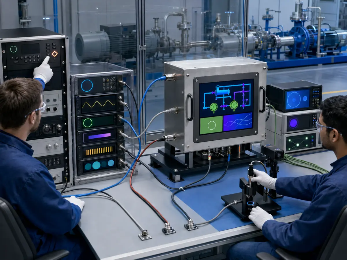
No single capacitor, UPS, or firmware delay solves every power problem. The design should start with the source characteristics, required ride-through time, permitted shutdown behavior, startup load, thermal limits, enclosure, maintainability, and hazardous-area implications.
Direct answer: Stable recovery may use coordinated power supplies, undervoltage lockout, reset supervision, sequencing, controlled discharge, adequate but bounded hold-up energy, surge and transient protection, watchdogs, startup delays, and firmware state management. The selected measures must be verified at voltage, temperature, load, and component tolerances.
How Do Reset Supervision and Hysteresis Prevent Boot Loops?
A supervisor can hold a processor or controller in reset until its supply is within a valid range and stable for the required time. Hysteresis separates the turn-on and turn-off thresholds so that small input movement does not repeatedly release and assert reset.
The circuit must coordinate with every relevant rail. Releasing the host while the touch controller or display bridge is still outside its operating range can reproduce the same intermittent startup problem at a different point in the system.
When Is Hold-Up Time or a UPS Useful?
Hold-up energy can bridge a short transfer event, keep a display available during a defined disturbance, or provide time for an orderly shutdown. A UPS may support a complete HMI or computer where continuity is operationally justified.
More stored energy adds space, heat, maintenance, aging, charging, fault, and end-of-life considerations. Batteries and energy-storage components can also affect hazardous-area assessment. The project should define the required load and duration instead of adding unmeasured capacitance or an unapproved backup supply.
Why Must LCD Power and Backlight Sequencing Be Controlled?
LCD modules specify relationships among logic power, data signals, reset, enable, and backlight. Driving signals into an unpowered panel, enabling the backlight before stable image data, or collapsing rails in the wrong order can cause a white flash, residual image, abnormal current, or unreliable startup.
The controller and cable design should implement the selected panel's timing and voltage requirements across cold start, warm restart, brownout, and rapid reapplication. A replacement panel may require different timing even when it uses the same interface family.
How Do Grounding and Electrical Noise Affect Recovery?
Contactors, motors, drives, solenoids, generators, and switching supplies can create conducted or radiated interference at the same moment the power network changes state. Ground bounce or transient coupling can reset a controller even when the steady-state input voltage appears acceptable.
Power quality, filtering, cable routing, shield termination, chassis bonding, isolation, protective devices, and return-current paths should be evaluated as one system. Related failure mechanisms are covered in How Does Electrical Noise Affect Oil and Gas Equipment Displays?.
How Do Hazardous-Area Requirements Affect Backup Power?
A UPS, battery, supercapacitor, added converter, protective device, or larger capacitor can change energy storage, heat, charging behavior, fault current, wiring, enclosure space, and surface temperature. It should not be added to an assessed hazardous-area HMI without engineering and certification review.
Loss-of-power and restoration procedures must also respect the protection concept, isolation method, permitted maintenance, and site rules. An industrial LCD or low-voltage supply does not by itself make the completed equipment suitable for an explosive atmosphere.
Claim: Reliable restart comes from coordinated thresholds, sequencing, energy storage, grounding, protection, firmware, and system architecture whose tolerances are validated together—not from one oversized power component.
4. How Should Engineers Validate Power-Loss Recovery?
A power switch demonstration proves only one abrupt interruption at one input voltage and temperature. Field equipment can experience partial dips, slow decay, brief recovery followed by another loss, phase-specific AC events, DC source impedance, transfer delays, and disturbances at different points in the boot process.
Direct answer: Build a test matrix from the actual supply architecture and equipment requirements. Apply defined residual voltages, durations, phase relationships, ramp rates, repetition intervals, source impedances, and restoration sequences. Test during boot, normal operation, configuration writes, active touch, communications, alarms, and shutdown while recording every subsystem's behavior.
Which IEC Tests Relate to Voltage Dips and Interruptions?
IEC 61000-4-11 defines test methods for voltage dips, short interruptions, and voltage variations for relevant AC-powered equipment with input current up to 16 A per phase. IEC 61000-4-34 addresses equipment above 16 A per phase. IEC 61000-4-29 provides methods for disturbances at applicable external low-voltage DC input ports.
These are basic EMC test methods rather than universal product acceptance specifications. The applicable product standard, equipment specification, installation, power network, risk assessment, and compliance plan determine which methods, levels, durations, operating modes, and performance criteria apply.
What Should a Power-Recovery Test Matrix Include?
Include nominal and boundary input voltages, cold and hot equipment, minimum and maximum load, brightness extremes, peripherals, multiple boot stages, active data writes, video presence or absence, network loss, and host/display power order. Repeat tests enough to reveal intermittent timing failures.
| Test Condition | Display-Side Check | System-Level Check |
|---|---|---|
| Brief voltage dip | Flicker, link reset, touch event | Continuous or defined degraded operation |
| Complete short interruption | Controlled blanking and restart | Recovery time and current data |
| Slow voltage decay or rise | No partial-rail latch or white flash | No boot loop or undefined state |
| Repeated cycling | Consistent image and brightness | No setting or storage corruption |
| Host-first/display-first startup | Video detection and touch enumeration | Correct HMI launch and scaling |
| Loss during alarm or command | Clear status after restart | Alarm history and actual process state |
Which Operating States Need to Be Tested?
Apply disturbances before the BIOS or bootloader starts, during operating-system loading, while graphics drivers initialize, during HMI launch, after steady operation, during touch enumeration, during a settings write, and while communications are reconnecting. Timing-sensitive defects often appear only within a narrow startup window.
Also test suspend, wake, remote restart, controller reset, source reconnection, and any service mode the production equipment supports. Use production BIOS, operating system, drivers, application, firmware, controller, panel, cables, and settings.
What Should the Pass Criteria Measure?
Pass criteria can cover maximum recovery time, absence of uncontrolled commands, correct image and resolution, touch availability, brightness state, current data, communication status, alarm preservation, settings integrity, event logging, remote diagnostics, and defined behavior after retry limits are reached.
“No damage” is insufficient. Temporary degradation may be acceptable in one product and unacceptable in another, but the allowed behavior must be documented before testing and must remain consistent with operational and safety requirements.
Why Should Temperature and Aging Be Included?
Capacitance, battery capacity, converter startup, LCD behavior, oscillator timing, and load current change with temperature and age. A system that bridges an interruption at room temperature with new components may reset at low temperature or near end of service life.
Validate critical thresholds and hold-up margins at relevant temperature and load boundaries. Component tolerance, wear, expected battery maintenance, replacement intervals, and lifecycle changes should be included in the design evidence.
How Should Test Failures Be Diagnosed?
Record the equipment input, internal rails, reset lines, enable signals, backlight current, video-link state, host logs, touch enumeration, application logs, and network status with synchronized timing. A video of the screen is useful but cannot show which internal event caused the failure.
Determine whether the fault belongs to the source, power supply, sequencing, controller firmware, panel timing, cable, host driver, operating system, application, touch interface, or network. Correct the root cause and repeat the full matrix because a longer delay can hide one race condition while creating another.
Claim: Power-recovery validation requires controlled disturbances, production hardware and software, boundary temperatures and loads, measurable pass criteria, synchronized diagnostics, and repeated testing across every credible operating state.
5. What Advantages Does XIANHENG Offer for Oil and Gas Display Projects?
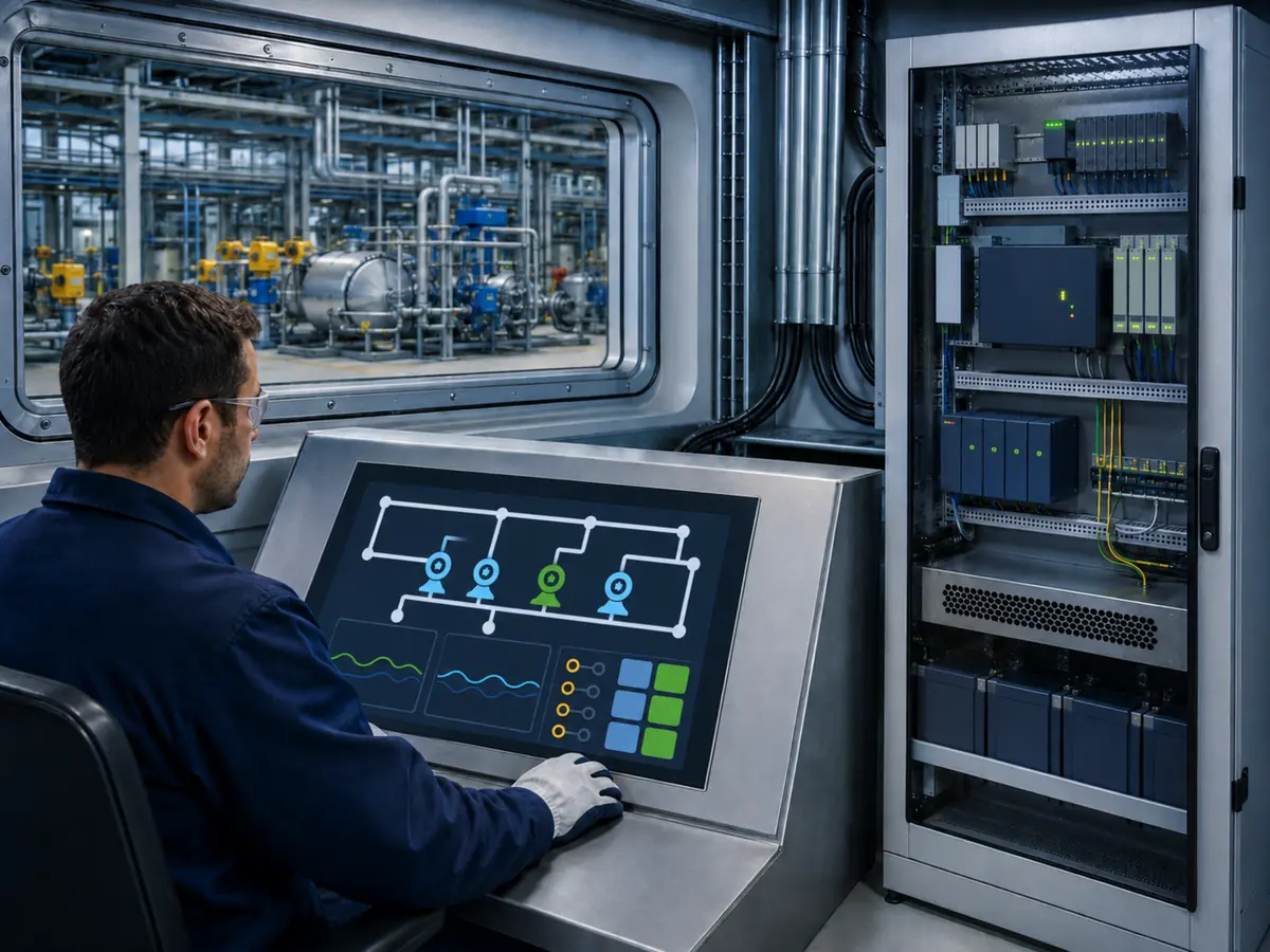
XIANHENG supports display integration for drilling controls, well-service equipment, analyzers, pumps, compressors, metering skids, pipeline stations, loading systems, refineries, offshore machinery, and remote HMIs. Support can begin with a new power architecture or an existing display that does not restart reliably.
Direct answer: XIANHENG can coordinate industrial TFT LCD selection, controller boards, controller firmware, power and backlight behavior, PCAP or resistive touch, customized cover glass, optical bonding, cables, drawings, samples, inspection, replacement analysis, and lifecycle planning. Customers can review panel starting points in the Industrial LCD Product Collection. Final equipment power design, control safety, hazardous-area conformity, EMC qualification, and approval remain with the responsible equipment manufacturer and certification parties.
How Can XIANHENG Review LCD Power Sequencing?
Customers can provide the panel datasheet, host specification, controller model, cable drawing, power rails, enable signals, backlight requirements, startup order, shutdown order, and recorded failure. XIANHENG can compare the intended sequence with the LCD and controller requirements.
A proposed panel replacement can also be reviewed for logic voltage, startup current, backlight driver, enable polarity, timing, connector, and discharge behavior. The customer then verifies the complete circuit and equipment under its required disturbances.
Can XIANHENG Support Controller Firmware and Auto Recovery?
For supported controller solutions, firmware can coordinate input selection, native panel timing, EDID or source behavior where applicable, backlight enable, stored settings, and startup after power is restored. The required behavior should be defined against the actual host rather than a generic signal generator alone.
Samples can be checked for cold start, warm restart, host-first and controller-first startup, input loss, and repeated cycling. Equipment-level pass criteria and final qualification remain the customer's responsibility.
Can XIANHENG Coordinate Touch Recovery?
The project can coordinate the touch sensor, controller, firmware, USB or I²C interface, reset behavior, cable, grounding, cover glass, and LCD as one subsystem. Testing should confirm enumeration, mapping, rotation, glove input, false-touch rejection, and recovery after each supported power sequence.
How Can XIANHENG Support an Existing Recovery Problem?
Useful evidence includes the original LCD, controller, touch and cable models; host output; power diagram; BIOS and operating system; controller firmware; input voltage waveform; internal rail measurements; reset signals; event logs; failure video; ambient temperature; and exact steps that reproduce the fault.
What Information Should Customers Send to Start?
Send the equipment type, installation country, supply type and range, AC or DC input, source and backup architecture, required ride-through or restart time, display size and resolution, host interface, LCD model, controller, touch interface, startup sequence, brightness behavior, temperature, EMC conditions, hazardous-area status, annual quantity, schedule, and lifecycle target.
To discuss an oilfield HMI, drilling-control display, pump or compressor touchscreen, pipeline-station LCD, offshore monitor, controller solution, customized cable, or obsolete display replacement, please reach out to XIANHENG.
Claim: XIANHENG can support the panel, controller, firmware, touch, cables, samples, replacement work, and lifecycle evidence needed for display recovery while keeping final power, safety, compliance, and equipment validation responsibilities clearly defined.


