
UV exposure can affect oil and gas equipment displays installed at wellheads, drilling sites, pipeline stations, tank terminals, loading systems, compressor packages, and offshore facilities. Direct sunlight is the most obvious source, but reflected sunlight and long-term exposure through an enclosure window can also age display materials.
The first symptom may not be an electronic failure. A surface treatment can lose performance, a printed border can fade, a plastic bezel can chalk, an adhesive edge can weaken, or an LCD polarizer can discolor. These changes may develop gradually and become visible only after months or years of outdoor service.
UV durability therefore depends on the completed display stack. The cover glass, coating, printed ink, touchscreen, bonding layer, perimeter adhesive, LCD polarizers, gasket, plastic parts, enclosure finish, cable jackets, and mounting orientation must be considered together.
Quick Answer: UV exposure can affect oil and gas equipment displays by causing yellowing, fading, color shift, haze, gloss change, coating degradation, ink loss, adhesive weakening, bubbles, delamination, polarizer damage, embrittlement, cracking, and loss of sealing. The risk depends on the solar spectrum, irradiance, cumulative radiant exposure, orientation, latitude, altitude, shading, glass transmission, surface temperature, humidity, wetting, chemicals, and service duration. Engineers should select UV-compatible materials, protect vulnerable edges, control solar heating, and validate production-intent materials and assemblies under a defined solar-radiation or weathering test with measurable optical, mechanical, touch, and sealing acceptance criteria.
Claim: High brightness, wide-temperature operation, and UV durability describe different requirements. None of these characteristics automatically proves the other two.
1. Why Does UV Exposure Matter in Oil and Gas Displays?
Outdoor oil and gas equipment can remain in service for many years, while the front of the HMI receives repeated daily solar exposure. UV energy can initiate photochemical changes in organic materials, and visible or infrared solar energy can raise the temperature of the glass, ink, adhesive, LCD, and enclosure.
Direct answer: UV exposure matters because it can progressively change the optical, chemical, and mechanical properties of coatings, polymers, inks, adhesives, polarizers, elastomers, and finishes. The damage is governed by the actual spectrum and accumulated exposure together with heat, moisture, chemicals, mechanical stress, and material construction.
Which Oil and Gas Installations Receive the Most Solar Exposure?
Exposed wellhead controls, drilling consoles, outdoor skids, pipeline stations, loading equipment, tank-farm HMIs, mobile service systems, and offshore deck equipment can receive direct sun. A sheltered screen may still receive reflected radiation from water, pale ground, metal structures, or nearby equipment.
Orientation and duty cycle matter. A horizontal or upward-facing display may receive different solar loading and retain more water or contamination than a vertical panel. A portable terminal can also be left face-up outdoors even when its normal operating position is shaded.
How Is UV Durability Different from Sunlight Readability?
Sunlight readability describes whether the operator can see the required information under bright ambient light. It depends on luminance, front-surface reflection, contrast, optical bonding, viewing angle, HMI colors, font size, and installation geometry.
UV durability describes how materials change after accumulated radiation exposure. A high-brightness LCD may be readable when new but still use a coating, ink, adhesive, plastic, or polarizer that requires separate weathering validation. Brightness selection is covered in How Bright Should Oil and Gas Equipment Displays Be?.
How Is UV Aging Different from Solar Heating?
UV radiation can break or rearrange chemical bonds in susceptible organic materials. Solar heating results from absorbed energy across a broader spectrum and can raise component temperature above the surrounding air. The two mechanisms can occur at the same time and can accelerate related failures.
A dark printed border can become hotter than the clear viewing area, increasing stress in the glass, ink, adhesive, and gasket. Thermal design must use the temperature at the display assembly rather than the forecast air temperature. The wider thermal requirement is reviewed in What Temperature Range Do Oil and Gas Equipment Displays Need?.
Does Cover Glass Automatically Protect Every Internal Layer?
No. Glass composition, thickness, coatings, lamination, printing, adhesive, and optical bonding determine spectral transmission. Some glass constructions reduce parts of the UV spectrum, but the exact protective effect must be supported by data for the finished stack.
Edges, cutouts, seams, rear surfaces, exposed adhesive, cable jackets, gaskets, and external plastic parts may not sit behind the same glass. A favorable transmission value for one clear glass coupon does not qualify every material in the HMI.
Claim: UV exposure should be specified from installation location, orientation, shielding, service duration, material stack, and combined environment rather than inferred from outdoor use or LCD brightness alone.
2. How Can UV Exposure Damage Display Materials and Operation?
UV-related deterioration can be cosmetic, optical, mechanical, or functional. A slight color change may be acceptable on a hidden bracket but unacceptable in the active viewing area, on an alarm indicator window, or on a marking required for operation.
Direct answer: UV exposure can change glass treatments, printed ink, polarizers, optical films, touch materials, bonding layers, adhesives, gaskets, plastics, paints, labels, and cable jackets. Possible symptoms include yellowing, fading, chalking, haze, loss of gloss, cracks, brittleness, shrinkage, swelling, edge lift, bubbles, delamination, reduced touch usability, and loss of sealing.
How Can Cover-Glass Treatments Change?
The glass substrate may remain stable while an anti-reflective, anti-glare, anti-fingerprint, hydrophobic, conductive, or other surface treatment changes. Weathering can affect transmission, reflectance, haze, color, gloss, surface energy, friction, scratch resistance, or coating adhesion.
A change in surface energy can also alter cleaning behavior. Contamination may spread differently, fingerprints may become harder to remove, or an incompatible cleaner may attack an already aged coating. Inspection should use controlled lighting and representative dark and light images.
How Can Printed Borders and Markings Degrade?
Printed borders, logos, button legends, warning areas, indicator windows, and decorative layers can fade, discolor, chalk, crack, lose adhesion, or become visible through a changed top layer. Dark inks can also absorb solar energy and create locally high temperatures.
Ink formulation, pigment, layer thickness, cure, printing method, glass preparation, backing color, exposure side, and contact with adhesive influence performance. Safety or operating markings should remain legible throughout the specified maintenance interval.
How Can LCD Polarizers and Optical Films Be Affected?
LCD polarizers and their adhesive systems are organic optical components. Excess radiation and temperature can contribute to discoloration, loss of polarization performance, shrinkage, bubbling, peeling, edge lift, or image nonuniformity when the module is not adequately protected for the application.
A bare LCD should not be installed where its polarizer receives uncontrolled direct sunlight. Cover glass, touch integration, optical filtering, bonding, enclosure geometry, and thermal design must protect the module without creating excessive heat or mechanical stress.
How Can Adhesives and Optical Bonding Change?
UV and heat can affect optical adhesive, perimeter adhesive, primer, foam tape, and laminated layers. Symptoms may include yellowing, haze, hardness change, loss of adhesion, edge lift, bubbles, cracking, or delamination between glass, touch sensor, bonding layer, and LCD.
Optical bonding can remove internal reflective surfaces and one open contamination space, but it is not automatically UV-qualified. Bonding chemistry, cure, thickness, edge protection, glass transmission, thermal expansion, repair method, and production process must be controlled.
How Can Touch Performance and Surface Use Change?
PCAP sensing electrodes may be protected inside the touch construction, but the cover coating, printed border, optical adhesive, sensor substrate, tail bond, controller cable, and edge seal can still age. Surface haze, friction change, cracking, or delamination can make accurate touch operation more difficult.
Resistive touchscreens can have an exposed flexible top layer whose UV and abrasion durability requires specific review. For either technology, testing should cover optical clarity, coordinate accuracy, false and missed touches, gloves, edge response, and recovery after cleaning.
How Can Plastics, Gaskets, and Cable Materials Degrade?
Plastic bezels, overlays, labels, connector parts, cable jackets, gaskets, foam, and enclosure coatings can discolor, chalk, harden, soften, crack, lose strength, or become brittle. A gasket can lose sealing performance even when its color change appears minor.
Material formulation, pigment, stabilizers, thickness, stress, compression, temperature, chemical exposure, and manufacturing process influence the result. Supplier material-family data should not be extended to an unverified color, grade, coating, or production process.
| Display Element | Possible UV or Weathering Effect | Primary Acceptance Check |
|---|---|---|
| Glass surface treatment | Haze, color, gloss, reflection, adhesion change | Optics, readability, cleanability |
| Printed ink or marking | Fading, chalking, cracking, edge lift | Color, legibility, adhesion |
| LCD polarizer or optical film | Yellowing, shrinkage, bubbles, nonuniformity | Image, contrast, color, edge condition |
| Bonding or perimeter adhesive | Haze, hardness change, loss of adhesion | Transmission, bubbles, bond integrity |
| Touch surface or sensor stack | Friction change, cracking, delamination | Accuracy, gloves, false and missed touch |
| Gasket, plastic, cable, or coating | Chalking, brittleness, cracking, property loss | Dimensions, strength, sealing, insulation |
Claim: UV aging can reduce readability, adhesion, touch usability, structural integrity, and sealing even when the LCD electronics continue to operate normally.
3. How Should Engineers Design a UV-Resistant Display System?
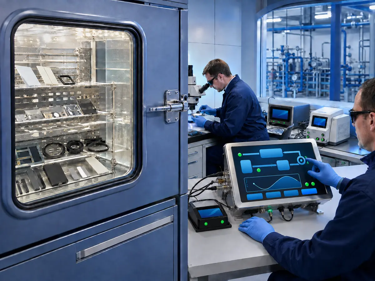
Design should identify every material reached by direct or transmitted radiation. Protecting the LCD polarizer while leaving adhesive edges, gasket surfaces, printed markings, cable jackets, or plastic bezels exposed can move the first failure to another part of the assembly.
Direct answer: Engineers should prepare an exposure map, select UV-compatible glass treatments, inks, adhesives, polarizers, elastomers, plastics, coatings, and cables, shield vulnerable edges, control solar heating, use suitable shading and orientation, define cleaning, and keep the approved material stack under configuration control.
How Should a UV Exposure Map Be Prepared?
Document installation location, latitude or project region, altitude where relevant, orientation, seasonal sun path, expected daily exposure, nearby reflection, shading, enclosure window, operating and storage position, surface temperature, humidity, wetting, salt, chemicals, cleaning, and service duration.
Map radiation paths to the front coating, glass, ink, touch sensor, bonding, polarizer, gasket, bezel, labels, buttons, enclosure finish, cable, and connector. Include abnormal positions such as an open service door or portable unit left face-up.
How Should Glass and Optical Filtering Be Selected?
Specify the glass composition, thickness, treatment, lamination, spectral transmission where required, optical clarity, impact requirement, touch compatibility, and temperature performance. Filtering should protect vulnerable layers without creating unacceptable color shift, transmission loss, reflection, or heat absorption.
The spectral data should represent the finished construction rather than uncoated base glass. Coating side, printing, adhesive, touch sensor, bonding, edge finish, holes, and transparent windows should match the production drawing.
How Should Inks, Bonding, and Seals Be Coordinated?
Choose inks, primers, optical bonding materials, perimeter adhesives, foam tapes, and gaskets for the intended radiation, temperature, moisture, and chemical conditions. Evaluate their contact interfaces because one aged layer can lose adhesion to an otherwise stable material.
Where practical, position printing and vulnerable adhesive behind protective glass and shield exposed edges. The production cure, layer order, thickness, overlap, compression, surface preparation, and storage history must be represented during validation.
How Should the Enclosure Protect Vulnerable Edges?
Use controlled bezel overlap, gasket position, covered bond lines, suitable drainage, protected cable exits, and enclosure geometry that reduces direct exposure at LCD and touch edges. Avoid pockets that trap water, salt, oil, or cleaning residue beside an aged adhesive or coating.
Protection must not apply uneven pressure to the glass, touchscreen, or LCD. It should also preserve ventilation, heat flow, connector access, cable bend radius, and serviceability under the equipment’s vibration and ingress requirements.
How Can Shading and Thermal Design Reduce Solar Stress?
A sunshade, hood, recessed mounting, suitable angle, reflective external finish, conductive heat path, controlled ventilation, or temperature-based brightness management can reduce direct radiation and internal temperature. These measures should preserve viewing angle, touch reach, drainage, cleaning access, and safe operation.
Designers should model or measure the hottest credible condition with the display operating. Maximum backlight power, dark printed borders, controller losses, enclosure color, solar direction, and low wind can combine to create temperatures that are not predicted from ambient air alone.
How Should Maintenance and Configuration Control Support UV Durability?
Define approved cleaning agents, wipes, inspection points, damage limits, and replacement criteria for coatings, glass, gaskets, labels, seals, and protective elements. Abrasive cleaning or an incompatible solvent can remove a weathered coating faster than sunlight alone.
The chemical relationship is reviewed in How Does Chemical Exposure Affect Oil and Gas Equipment Displays?. Any change to glass, coating, ink, adhesive, gasket, plastic, cable, shade, or cleaning process should be reviewed against the UV evidence.
Claim: UV-resistant display design protects the complete material stack, controls radiation and temperature at vulnerable edges, and preserves the validated construction through production and maintenance.
4. How Should UV Resistance Be Tested and Validated?
UV testing should reproduce the intended radiation path and relevant weathering conditions. A material coupon can compare formulations, while the assembled HMI is needed to reveal optical interactions, shaded zones, hot borders, exposed edges, joint stress, and functional behavior.
Direct answer: Engineers should define the light source, spectral distribution, filters, irradiance, radiant exposure, chamber and specimen temperature, humidity, wetting or condensation cycle, orientation, powered state, sample mounting, duration, inspection intervals, recovery, and acceptance criteria. Production materials, layer order, cure, compression, and enclosure geometry must be represented.
Which UV or Solar-Radiation Test Method Should Be Used?
The equipment requirement determines the final method. IEC 60068-2-5 specifies methods for testing equipment or components under simulated solar radiation at ground level and provides weathering guidance.
ISO 4892-2 addresses xenon-arc exposure of plastics in the presence of controlled temperature, humidity, or wetting. ASTM G155 provides procedures for operating xenon-arc apparatus. These methods require project-specific exposure and evaluation requirements; their names alone do not establish a pass condition.
Which Test Parameters Must Be Recorded?
Record the lamp and filter system, controlled wavelength band, irradiance, accumulated radiant exposure, exposure cycle, black-panel or black-standard temperature where applicable, chamber air temperature, relative humidity, spray water, condensation, specimen position, distance, rotation, interruptions, and calibration status.
Different filters and cycles can create different material responses. Reports should identify the exact conditions so results are not compared across chambers or laboratories without evidence that the exposures are equivalent for the material being evaluated.
Why Should Coupons and Production Assemblies Both Be Tested?
Coupons support controlled comparison of glass treatments, inks, adhesives, plastics, elastomers, coatings, and cable jackets. They allow measurements such as color, gloss, haze, mass, dimensions, hardness, tensile properties, adhesion, or retained strength.
Assemblies reveal transmitted radiation, layer interaction, masked and exposed areas, edge attack, differential heating, gasket compression, mounting stress, bubbles, touch behavior, and image effects. A coupon should not qualify a finished stack that has different interfaces and stresses.
Can Accelerated Test Hours Be Converted Directly into Outdoor Years?
Not reliably without a validated correlation for the material, exposure cycle, climate, orientation, and failure mechanism. Accelerated weathering changes irradiance, temperature, moisture cycles, and exposure continuity, while field conditions vary by season, location, shade, contamination, maintenance, and equipment use.
Use accelerated tests to compare candidates, expose weaknesses, and demonstrate performance against a defined requirement. If a service-life claim is needed, correlate laboratory results with relevant outdoor exposure or established product evidence rather than applying a universal hours-to-years factor.
What Should Be Measured Before, During, and After Exposure?
Possible checks include appearance, color difference, transmission, haze, reflectance, gloss, coating and ink adhesion, print legibility, bond strength, bubbles, delamination, cracks, dimensions, hardness, gasket compression, seal performance, cable insulation, image quality, luminance, contrast, and touch accuracy.
Record baseline measurements and inspect at planned intervals. Some changes are temporary after heating or moisture, while other damage becomes visible only after recovery, thermal cycling, flexing, cleaning, or a later ingress test.
How Should Combined Environmental Aging Be Addressed?
Real outdoor weathering combines solar radiation with heat, cold, humidity, condensation, rain, salt, chemicals, abrasion, and mechanical load. UV can embrittle a seal before vibration or cleaning, while moisture can enter a coating or bond that has begun to crack.
The validation plan should define representative preconditioning and sequence without combining conditions arbitrarily. The broader application relationship is reviewed in Why Does Oil and Gas Equipment Need Industrial LCD Displays?.
How Do Hazardous Areas and Product Changes Affect Approval?
A changed glass, filter, coating, ink, adhesive, gasket, plastic, cable jacket, shade, enclosure finish, or cleaning process can affect an assessed hazardous-area configuration. UV aging may also change electrostatic behavior, window retention, sealing, flame properties, bonding, or enclosure integrity.
The responsible manufacturer and certification parties should review these materials and changes against the approved protection concept. UV resistance does not independently establish hazardous-location conformity. Approved materials, drawings, suppliers, cure processes, inspection limits, test conditions, and alternatives should remain under configuration control.
Claim: UV validation requires a documented spectrum, irradiance, radiant exposure, temperature, moisture cycle, production material stack, objective measurements, recovery period, and configuration-control plan.
5. What Advantages Does XIANHENG Offer for Oil and Gas Display Projects?
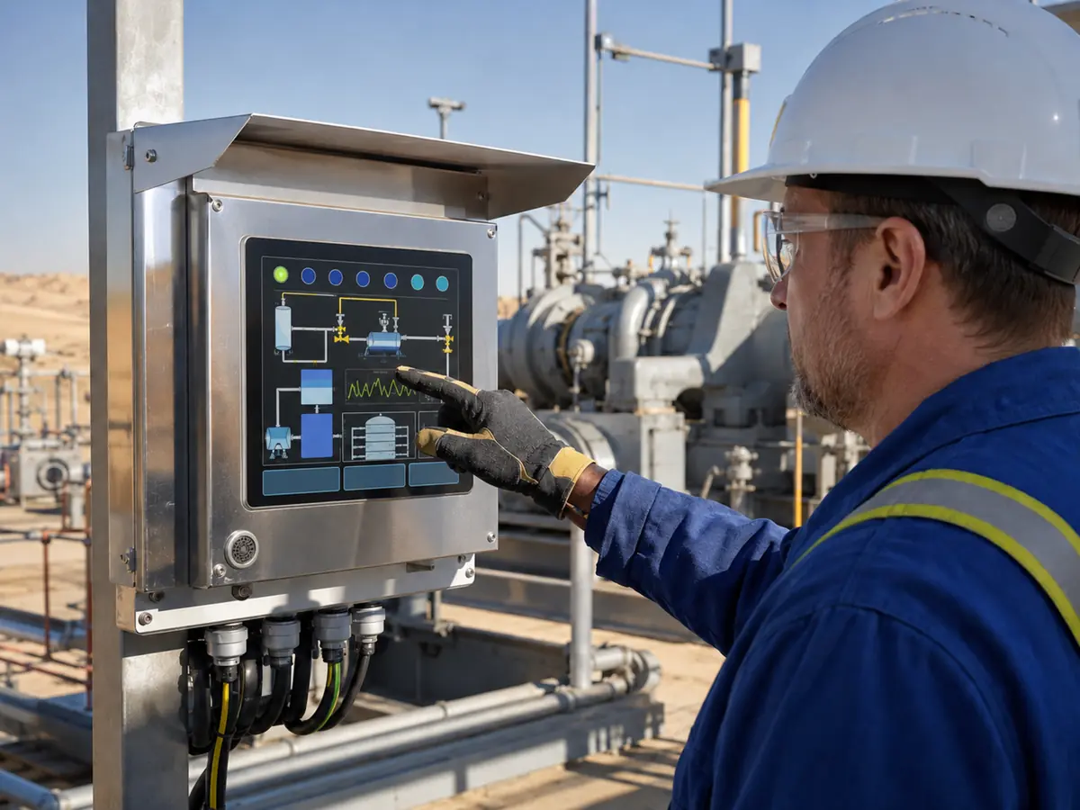
XIANHENG supports display projects for drilling controls, well-service equipment, pump and compressor packages, metering skids, pipeline stations, tank terminals, refinery machinery, loading systems, offshore equipment, and remote industrial HMIs. Support can begin with a new outdoor design or an existing display showing weathering-related deterioration.
Direct answer: XIANHENG can help customers compare industrial TFT LCDs and coordinate PCAP or resistive touch, customized cover glass, supported optical treatments, printed borders, optical bonding, perimeter interfaces, controller boards, firmware, customized cables, drawings, samples, inspection, replacement analysis, and lifecycle planning. Customers can review panel starting points in the Industrial LCD Product Collection. Final weather protection, enclosure design, UV-life requirement, hazardous-area conformity, and equipment qualification remain with the responsible manufacturer and certification parties.
How Can XIANHENG Help Compare Candidate LCDs?
Customers can provide the installation location, orientation, sunlight and shading conditions, enclosure drawing, service-life target, desired size and resolution, brightness, temperature range, touch method, host interface, panel cutout, annual quantity, and existing UV or weathering requirement.
XIANHENG can compare candidate panels across polarizer exposure, active area, outline, brightness, temperature, interface, connector, touch integration, lifecycle status, and available material information. The LCD remains one part of the finished UV-protection system.
Can XIANHENG Customize Glass, Printing, and Touch?
XIANHENG can coordinate cover-glass outline and thickness, printed border, logo, viewing window, holes, edge processing, supported surface treatments, PCAP or resistive touch, sensor tail, controller, and firmware. UV and weathering requirements can be included in drawing review and sample planning.
The customer should validate the production glass, treatment, ink, touch, bezel, shade, gasket, cleaning process, optical performance, and equipment operation under the defined exposure conditions.
Can XIANHENG Support Bonding, Controllers, and Cables?
XIANHENG can coordinate optical bonding or supported perimeter interfaces according to the selected LCD, touch, glass, temperature, optical, mechanical, and weathering requirements. Controller input, native output, firmware, timing, power, backlight control, connectors, and cables can be reviewed as one display subsystem.
Customized cables can follow the required connector, pinout, length, shielding, jacket, direction, bend limit, and strain relief. Exposed cable and connector materials remain part of the equipment-level UV, temperature, ingress, and chemical validation.
What Information Should Customers Send to Start?
Useful inputs include the equipment type, installation region, display orientation, direct or filtered sunlight, daily exposure, shade, enclosure window, target life, glass and coating requirements, printed ink, touch, bonding, gasket contact, temperature, humidity, rain, salt, chemicals, cleaning, vibration, classified or non-classified area, annual quantity, schedule, and replacement plan.
To discuss a UV-resistant oilfield HMI, drilling-control touchscreen, pipeline-station LCD, outdoor compressor display, tank-terminal monitor, offshore display assembly, customized cover glass, bonded touchscreen, or weathered-display replacement, please reach out to XIANHENG.
Claim: XIANHENG supports oil and gas UV-resistance projects by coordinating the panel, touch, glass, printing, treatments, bonding, controller, firmware, cables, samples, inspection, replacement work, and lifecycle while keeping final equipment responsibilities clearly defined.


